During the last year, we built a test piece of the fs36’s wing. We will tell you about the whole process in a series of articles.
Design work on our newest prototype, the fs36 “FlyByWire” is progressing quite well and CAD (Computer-Aided Design) work is becoming more and more detailed. During the whole CAD work, a thought inevitably comes to mind: “Is my design buildable and do the kinematics work as expected?”.
One way to verify this is to build a test piece, segments of the complete wing. Considering how unconventional a prototype the fs36 is, with its fowler flap and electronic flaperon actuators, test pieces are crucial. Not only can one test construction methods and kinematics, but also mold making processes in a smaller scale. Through this, one can learn lessons which will help in building the wing molds, the test wing, and finally the actual flying wings.
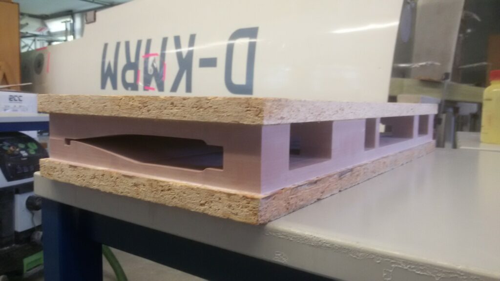
The current surface model of the plane during the start of this project was taken as the basis of the following work. From this, an as exact as possible cross section was set, which in this case was determined by the position of the outermost flaperon actuator. To simplify the building process, the profile was simply extruded into a rectangular wing section, which created the base for the CAD model used for internal design work and mold making. The width of the test piece was set at 50 centimeters (19,7 inches) to reduce the amount of work needed for the test piece. In this small region, the flaperon actuator, which is to be fixed to the fowler flap, along with the mechanical control rods and rails of the fowler flap have to fit.
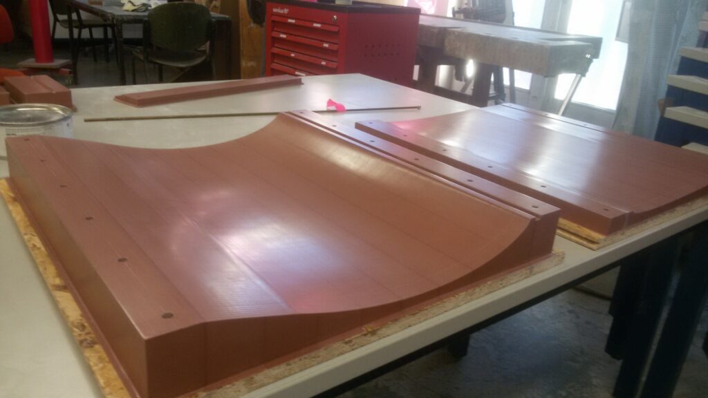
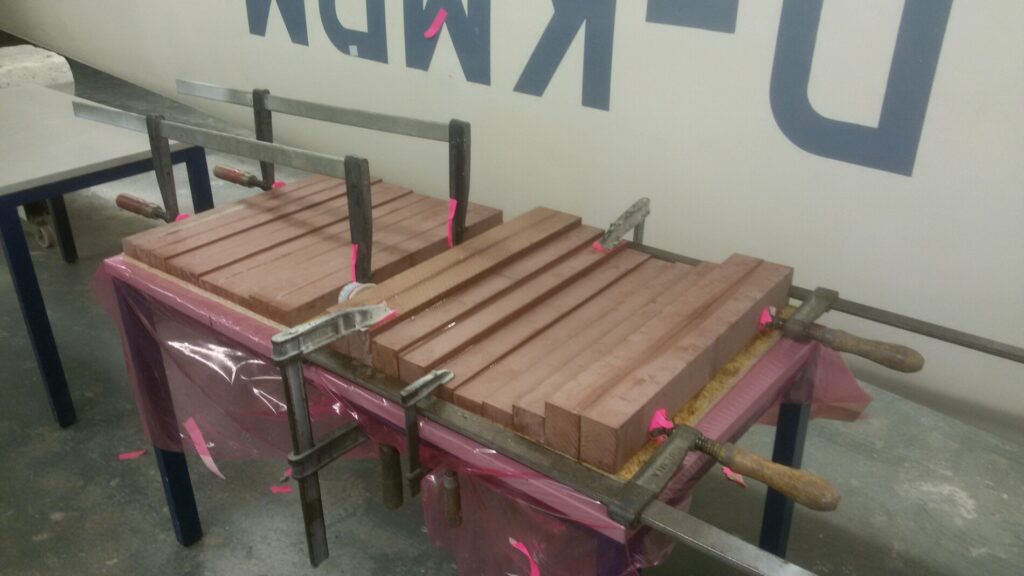
To save time, mold making took place in parallel to design work. Starting with the upper and lower skin form of the wing, which make up the largest mold parts of a wing in a semi-monocoque design. Other than that, other molds were required to build the wing (e.g. leading edge molds, flaperon and fowler flap molds, molds for the ribs and spar, etc). To create the molds from CAD models, we stuck polyurethan blocks to the required sizes and milled them with our CNC milling machine, which we recieved from the company Gühring. After we were done with the milling process, we turned our attention to the molds of the test piece, which we’ve prepared for the building process.
In the video below is a time lapse of the milling process on one of the molds for the fowler flap and flaperon.
Author: Tim Podufal

Funded by the Federal Ministry for Economic Affairs and Climate Action