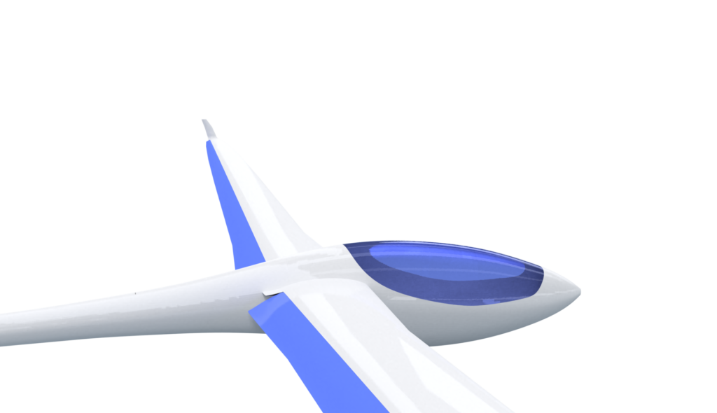
Our newest project, the fs36, will be a fly-by-wire sailplane with Fowler flaps, an idea first attempted by the Akaflieg Stuttgart with the fs34 Albatross. Generally, sailplanes with a variable wing area are designed to achieve an advantage in thermalling by increasing their wing area, while during high speed flight, the flaps are raised, giving said sailplanes a comparable wing area and wing loading as a standard sailplane. Since experience has shown that the gains achieved with the flaps lowered can’t usually be taken advantage of in competitions, we have decided to try another direction. Instead, with the flaps lowered , our design will have a comparable wing area as a standard high-performance sailplane with an 18m wingspan, ca. 10m2. Raised, the wing area is reduced to approximately 8,5m2, giving it an advantage in high-speed flight. In the end though, the fs34 wasn’t built due to the necessity of creating too many holes in the wing’s ribs to accomodate the flap mechanism. With the fly-by-wire system however, the construction of our Fowler flap design has become a possibility.
Theory
The flaps are to be extensible over almost the entire wingspan. This of course brings with it some challenges. If the wings bend in flight, the flap mus also be able to deform elastically. Of course, with the flaps lowered, this is only possible to a limited extent as the bending radius of the flaps is larger than that of the wing. Therefore, the entire flap system is to be separated into four pieces per wing, with a length of 2 meters respectively. Each flap runs on three track pairs and is driven on two separate points. This all allows it to follow the wing’s bending. One to two ailerons are fitted on each flap since the application of the necessary amount of force with actuators is a large challenge.
To gather some experience and get a feeling for the entire design, things which are important in the design and construction phase, we will test everything in test pieces of wings.
The Design of the Flaps’ Drive System for the Test Piece
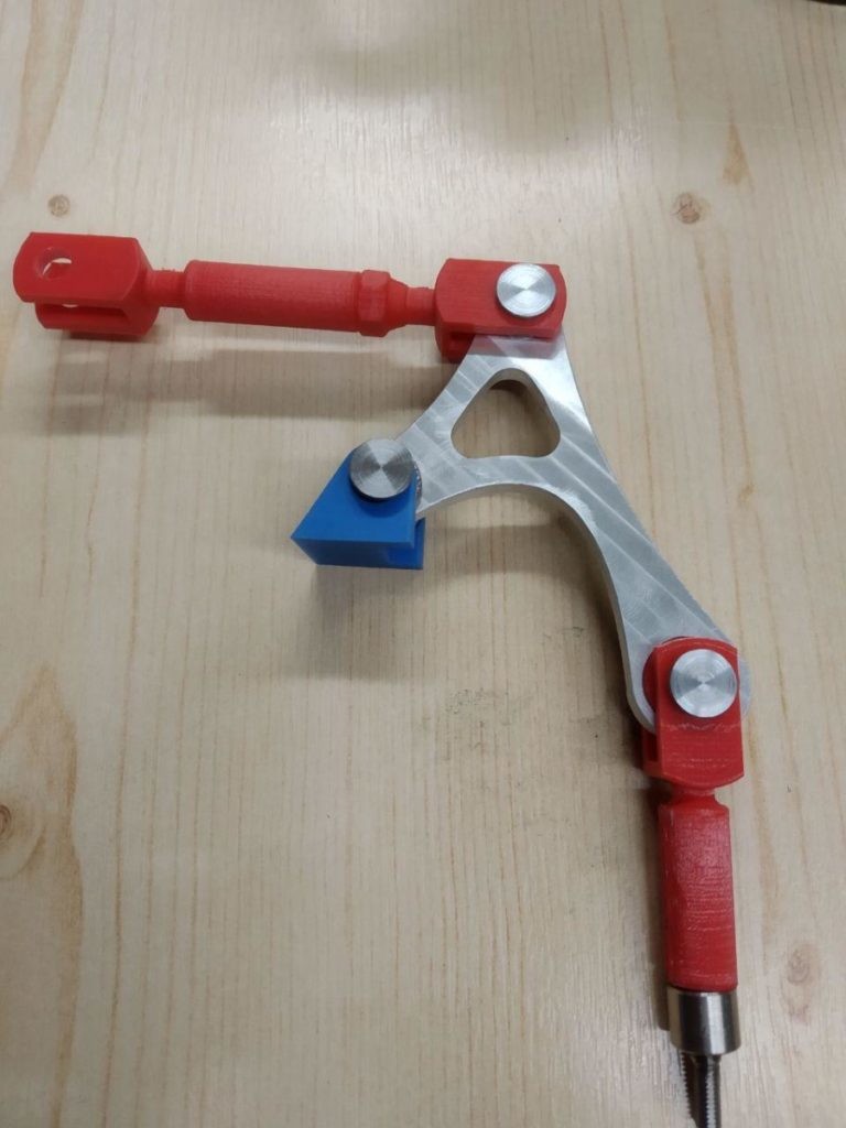
The flaps are to be driven by control rods in the wing. These are all controlled by an actuator in the fuselage, which operates all the flaps simultaneously. This means that the flaps will remain in a symmetrical deflection in case of an actuator failure.
The control rods travel a certain distance, however the flaps extend percentually along the wingspan, extending approximately 120 mm near the root and 30 mm near the tip. Therefore, I require a lever which can translate the lengthwise motion of the control rod into the retraction/extension motion needed for the flaps.
The lever rotates on a plane along the axis and translates said motion. A further challenge is creating the rod connecting the flap and the lever. On extension, the flaps move backwards and rotates slightly downwards around a specific point outside the wing. They rotate around this point as they extend further near the root than near the tip. The path of each point of the flap thus lies on a spherical surface and the above rods have to be able to even out the difference between the planar movement of the lever and the circular motion of the flaps. This challenge is further exacerbated by a lack of space near the wingtip.
To this end, I require two ball-and-socket joints. The joint on the flap has to be able to move through a 12 mm large hole and also has to be rotationally symmetric around the axis of the rod. There aren’t many joints that can be used for this purpose and at the moment, we have a self-designed joint in use.
On most mounts for single axis movement, plain bearings are used. When compared to ball bearings, the former have the advantage of a lower space requirement and a long service life with less friction.
First Fabrication Attempts
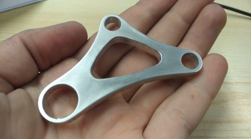
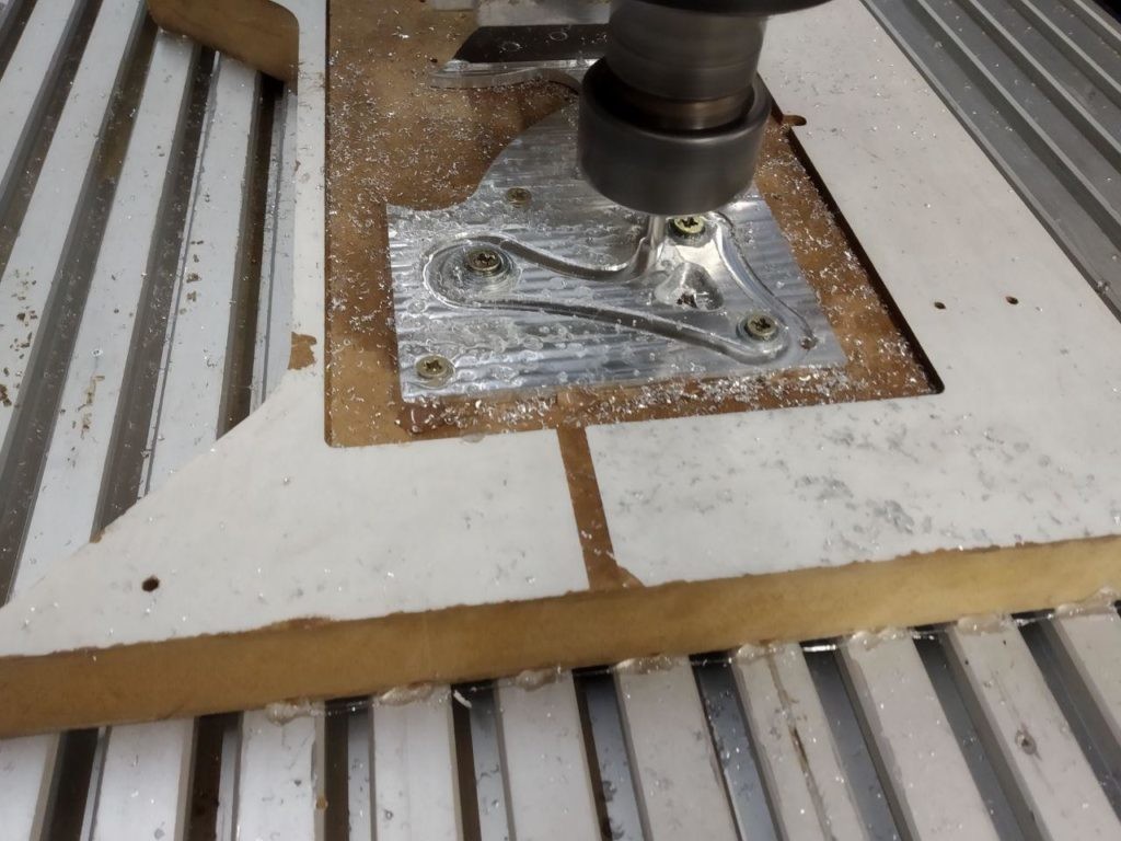
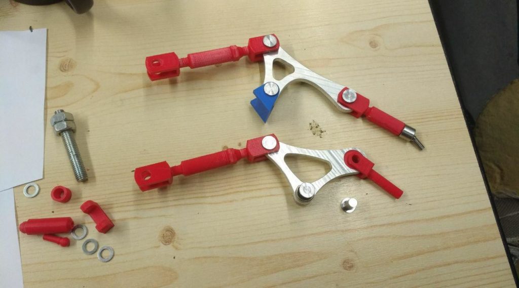
After spending some time designing the parts to a satisfying degree, we started fabrication of the first parts. In the following, the levers and control rods for the outermost flap can be seen. The lever itself was milled from an aluminium block with a CNC machine while the control rods were 3D-printed. From the pictures, one can see how small the entire assembly is.

The Tracks for the Test Piece
As for the tracks, we have the above mentioned problem that the flaps move in a circular motion. Said motion has to be generated by the tracks. This made designing them more complicated. Currently though, we have a few tracks, for which we have a good feeling. This theme has already become the subject of multiple theses, such as Paul von Bieberstein’s. We will now attempt to wrap up the design phase of the tracks and build the test piece of the wing.
Author: Felix Johnke
Supported by the Federal Ministry of Economy an Environmental Protection