After failing to update you folks on the progress of our little project in the last few months, it’s only fair to give a more detailed report on how far we are. In our defense though, the reason for the delayed reveal has more to do with our inability to do PR work than with problems in the project.
So what’s happened so far?
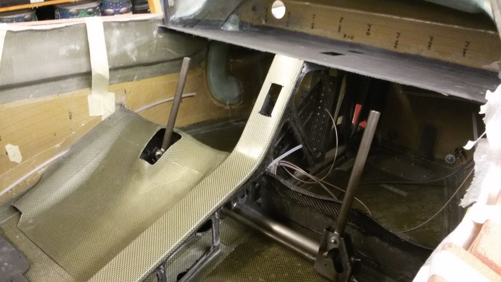
Let’s start with the controls: A welding frame was built for the necessary parts and said parts were then welded. Apart from powder coating, these parts are practically complete. The controls were then temporarily installed with rod end bearings and worked as planned. The stops for the control surfaces were then marked.
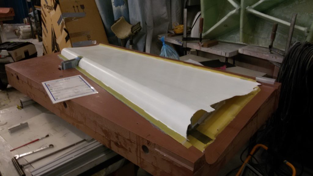
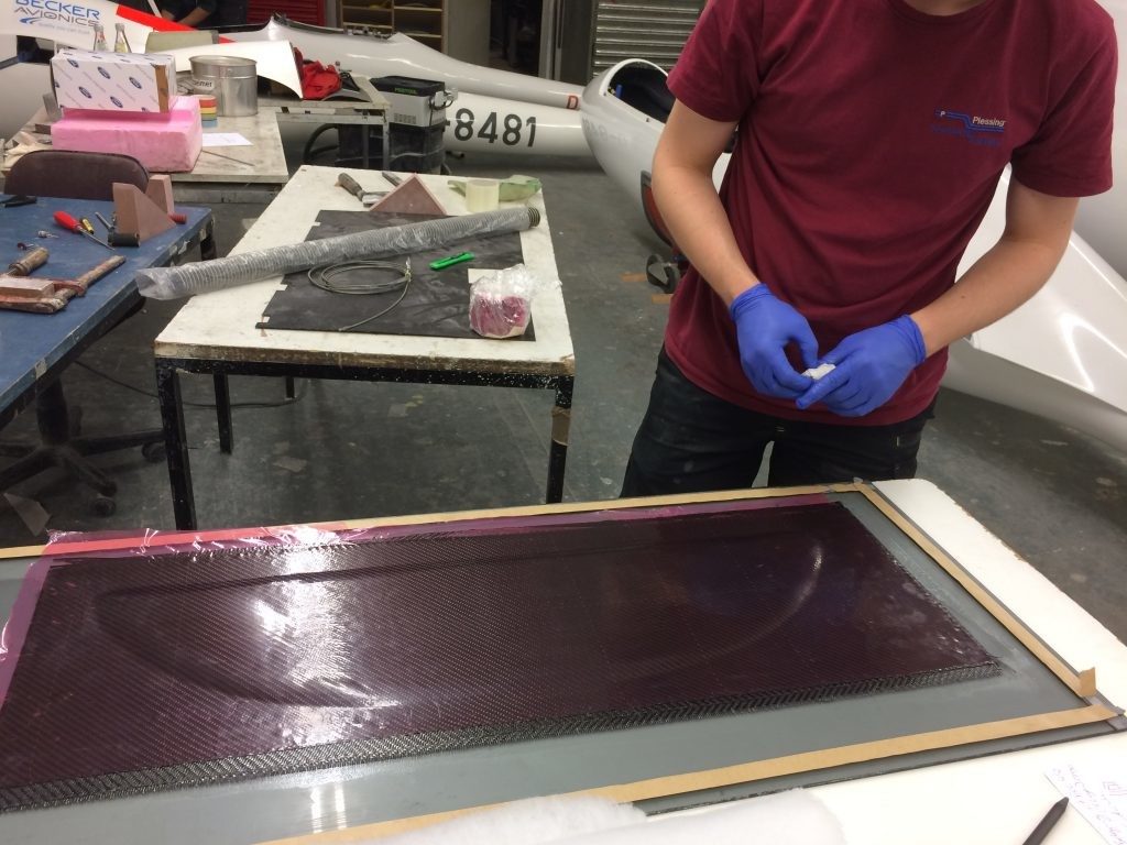
The rudder was succesfully removed from its mold, demonstrating the desired, in other words low, weight and residual torque. Furthermore, we built and installed the mounting for the rudder’s mixer in the fuselage. The fittings for the rudder have also been welded and the bushings and bolts have been made. After a few minor adjustments, the rudder will soon find its way onto our plane as planned.
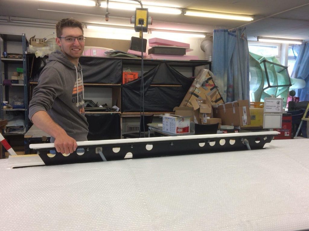
We’ve also made progress with the airbrakes as well: Two mounted ball bearings with CFC mounts were affixed inside the fuselage. The airbrake handle was milled from aluminium. It was then installed and is fully functional. In the wings, the airbrakes themselves were also completed, allowing for tests from the cockpit. Just like with the controls, only the surface treatment of the metal parts remains.
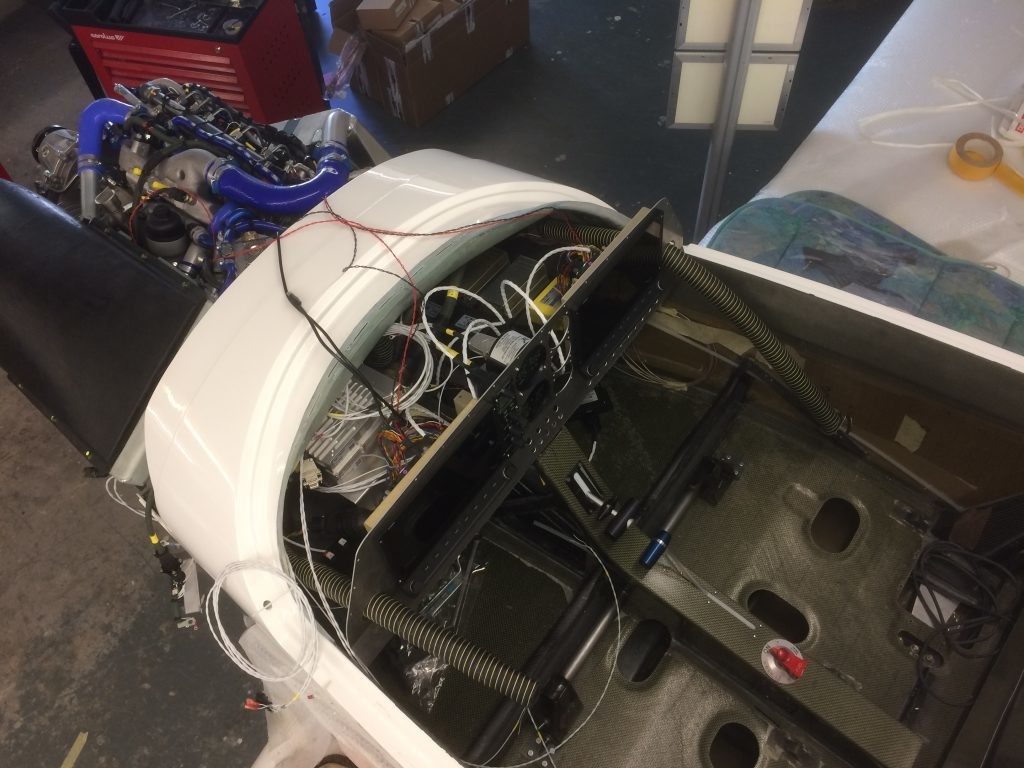
Central console with installed controls Rudder in its form “Audi” holding up an airbrake Timmäh working on one of the cockpit partitions
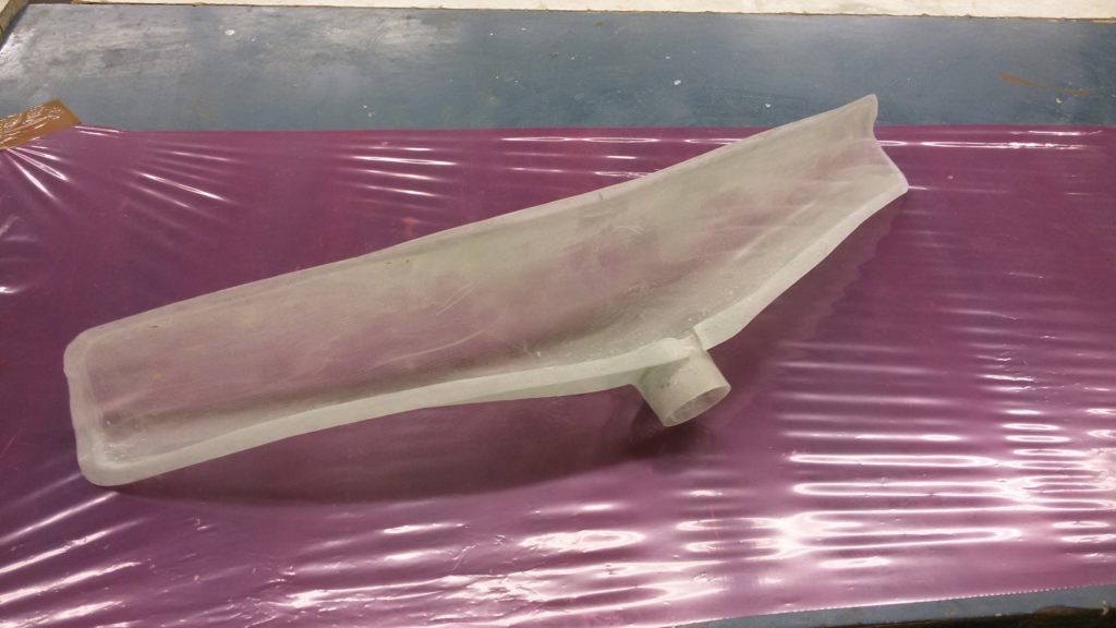
The controls aren’t the only new additions to the cockpit though: Two CFC plates were added to the central console for the laying of the cables. A polyamide guide was also installed in the slit for the airbrakes lever to help seal it. Furthermore, more holes were drilled in the firewall for the heater, cables, and all the things needed for the rudder pedals. Air ducts for cold air in the instrument panel and for heating the canopy were built next. To this end, molds had to be built, oftentimes inside the fuselage, to ensure that they will fit perfectly. The slits for warm air to the canopy are located on the instrument panel’s newly built top cover.
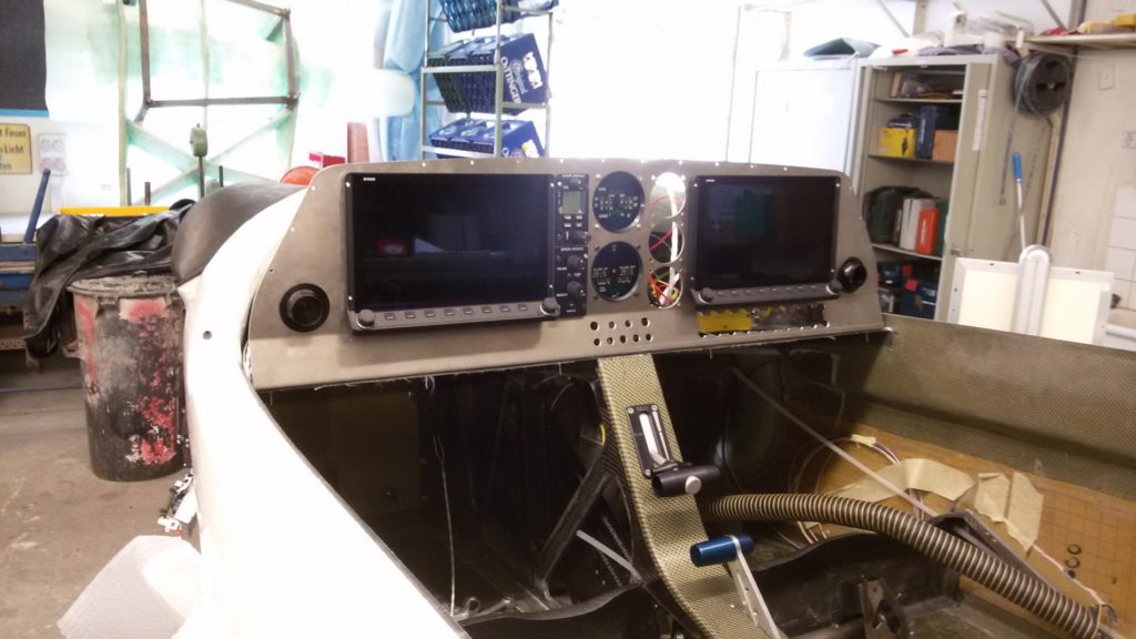
Assembly of the electrical system has shifted into overdrive. Both the engine electronics and the instruments are to be connected to each other via switches, fuses, and many, many cables. It’s all still very chaotic at the moment, though slowly but surely, we’re starting to get a good outline of the whole system.
Instrument panel with the Dynon SkyView HDX displays Warm air distributor Air distributor The chaos behind the instrument panel – still a few things to do
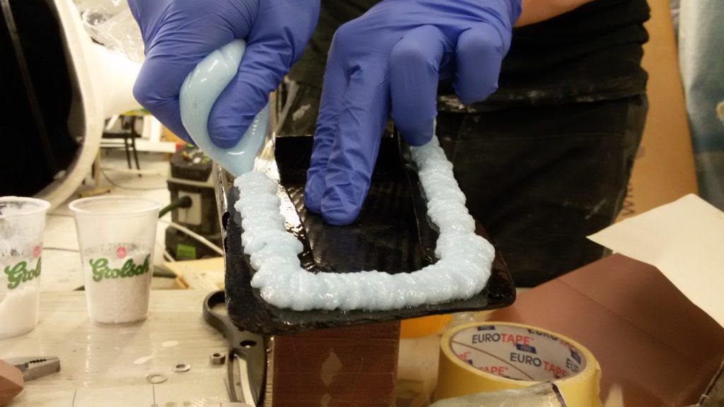
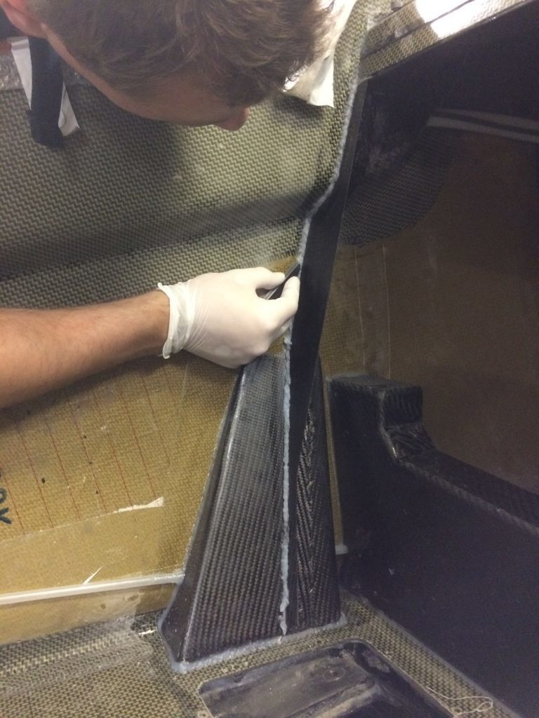
For the completion of the main undercarriage, two things were missing, namely the mountings and fuselage reinforcements, which would apply the forces as tangentially as possible into the fuselage wall. More molds had to be built for both CFC parts. These parts were then stuck to the fuselage with resin. Furthermore, the cockpit rear wall, which separates the cockpit from the fuel tank, could be built behind the mountings. For that, a mounting was built around the inside of the fuselage, with the wall built separately before being screwed on. The wall itself was built in the workshop of the Akaflieg Esslingen, with which we currently have a workshop cooperation.
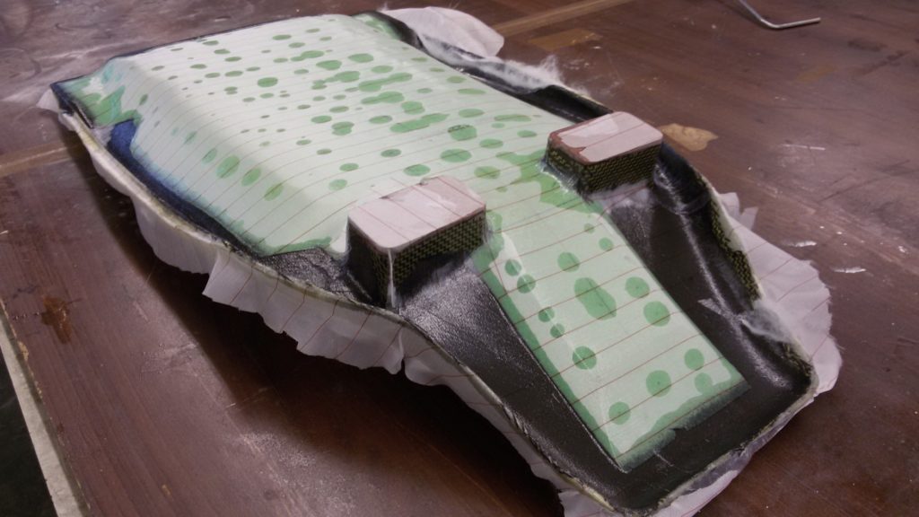
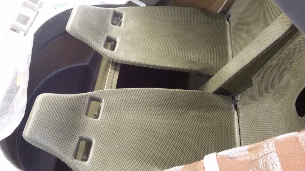
We could also finally build the seat buckets. Both parts, which were built from a carbon fiber-kevlar sandwhich hybrid, were built using the same form. Hinge mountings for these were also built and affixed to the cockpit floor and seat tests were done, proving to be quite comfortable.
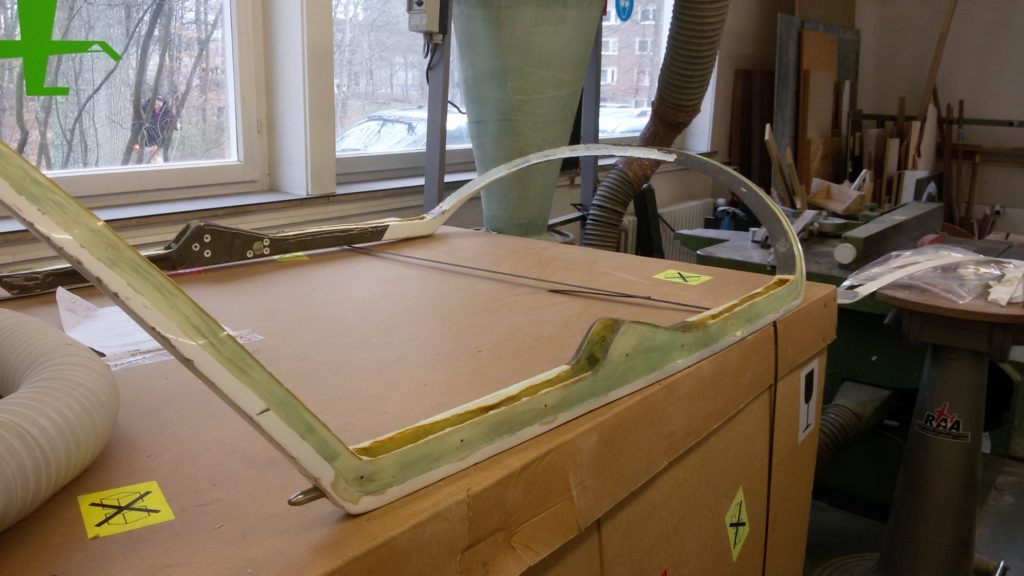
Mounting of the fuselage reinforcement Seat bucket in its form Installed seat buckets Canopy frame with its core removed Building of the cockpit rear wall’s mounting
Progress has been made with the canopy as well: An old canopy frame from a Dimona was taken and its core was removed. It was then given carbon fiber reinforcements. This led to a large reduction in weight and an increase in stiffness. Carbon fiber rods were then bought and used to replace the original, heavier steel ones in the canopy’s locking mechanism. Only thing left to do is giving the frame a new paint job and sticking the canopy glass on it.
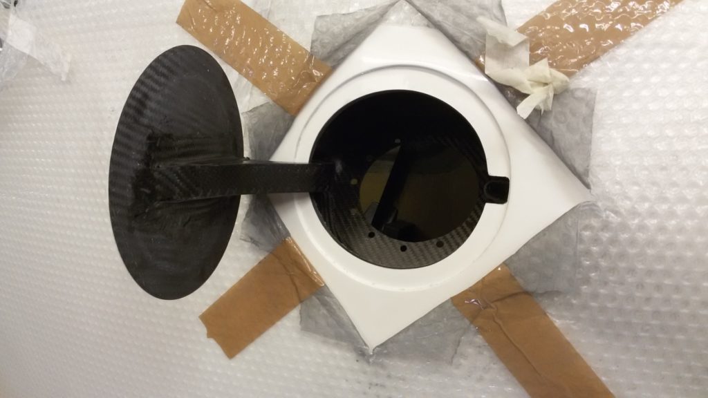
Up next is the fuel system: A fuel tank system, which was developed as part of a bachelor thesis, was installed in the fuselage. A cap for the fuel tank on the fuselage skin was also built. Steel lashing straps to secure the fuel tank and their mating parts, which are made of CFC, were then fitted to the fuselage. After the throttle system was assembled inside the fuselage, the required length of the fuel lines could finally by measured, meaning we could finally order them.
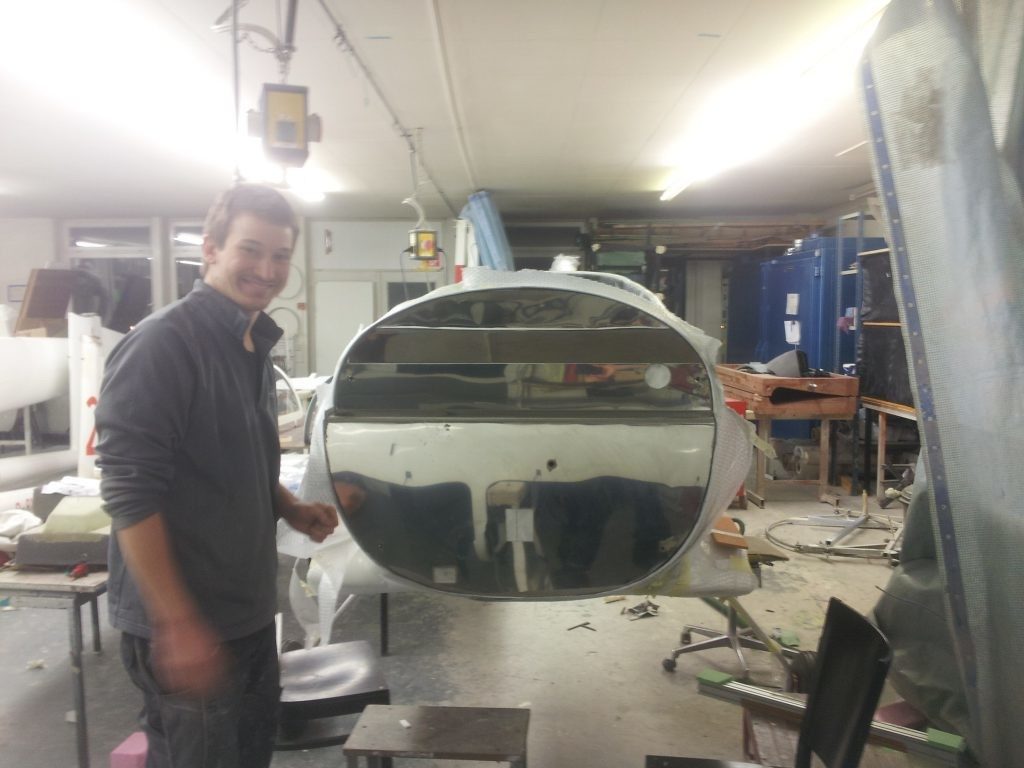
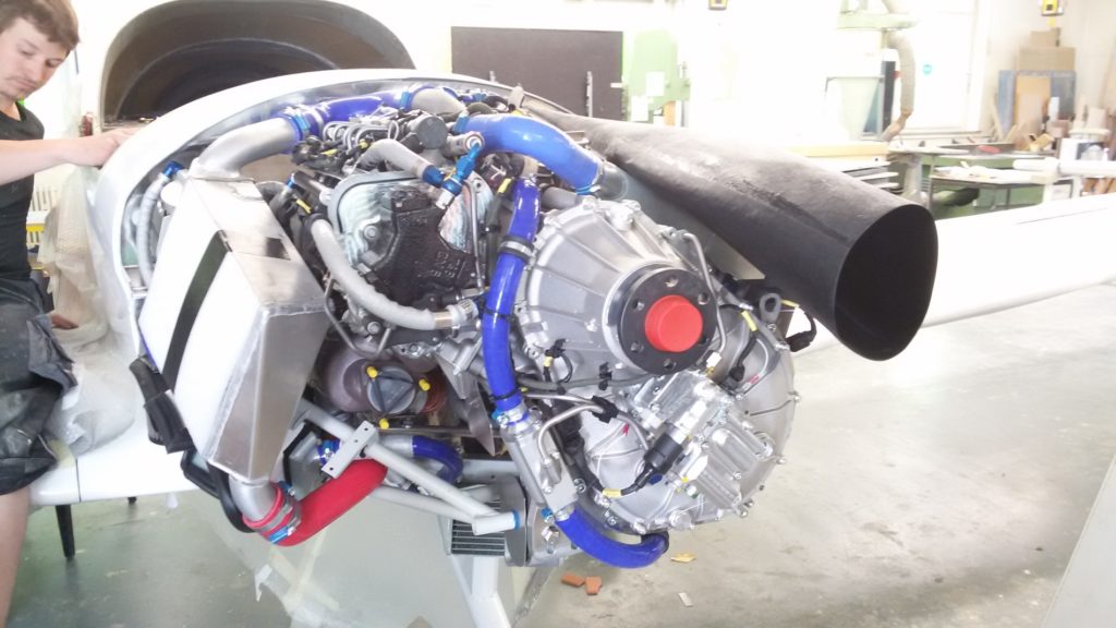
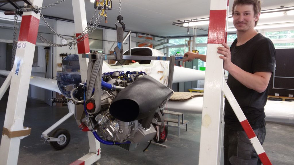
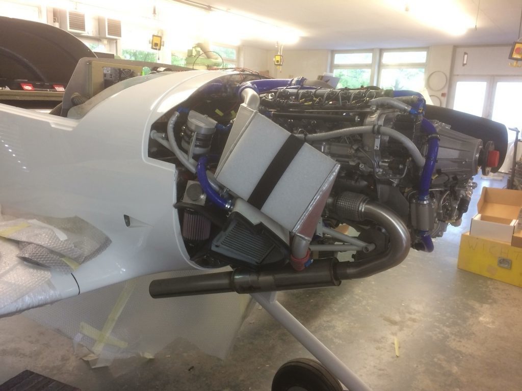
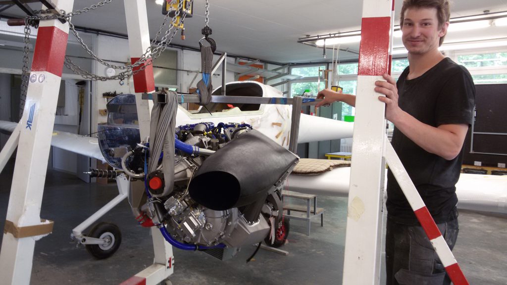
There are also some noticeable changes to the engine area. As one can see, the firewall has been installed. The engine itself was recently sent to Technify Motors again, where the cabling, alternator regulator, and coolant sensor were switched out for those from the Cessna’s system. That way, we could take over the electrical system from an existing system. Furthermore, we received the missing parts, such as the exhaust and fittings for the batteries needed for setting the propeller’s pitch, from Technify. For this and more we extend our gratitude to the company in St. Egidien, which never ceases to amaze us with their uncomplicated and quick assistance.
Fuel tank cap Firewall post-installation Installed engine Rospa with the CD-155 engine The installed engine finally has an exhaust!
The wheels are being finalized as well. We received two new wheel axles from Beringer Aero since the old ones obstructed the brakes. The current nose wheel will also be replaced by a new one from Beringer in the coming weeks.
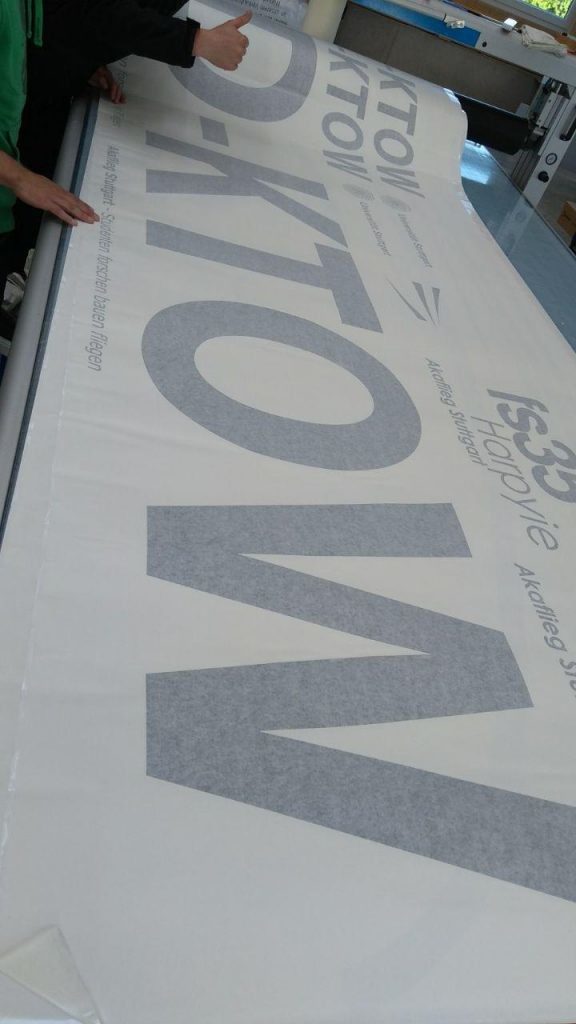
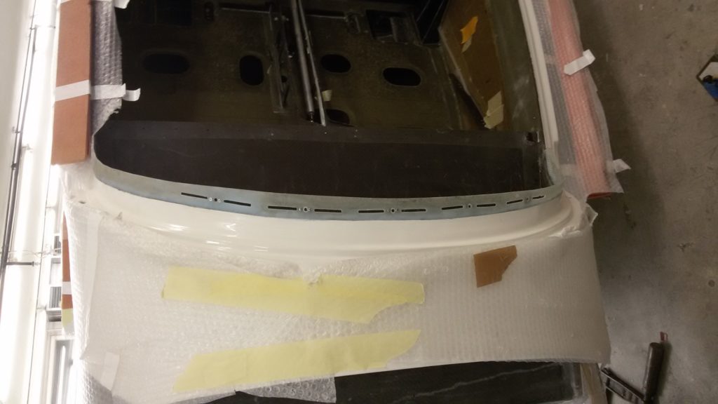
And finally something to looks: The decor and registration number for the fs35 were sent to us by Daiber Werbetechnik and our members can’t wait to stick them on the plane. Nevertheless, we would like to paint the interior first. To that end, we’ve removed as much as we could from the plane and masked the rest to protect them from swarf and paint dust.
