Fits, wobbles, and gets air
Of course, a finished fuel system is indispensable for the first run of our engine. This is another area where a lot has happened in recent months. Since the tank has been waiting for installation for more than a year now, it’s about time it gets its own seat belt. It is fastened with steel lashing straps, which secure the tank with various loads or a crash. For this purpose, special buckles according to the LN standard were made, and the matching fittings were installed in the fuselage. Sponge rubber will protect it from abrasion while allowing freedom of movement with temperature or pressure differences.
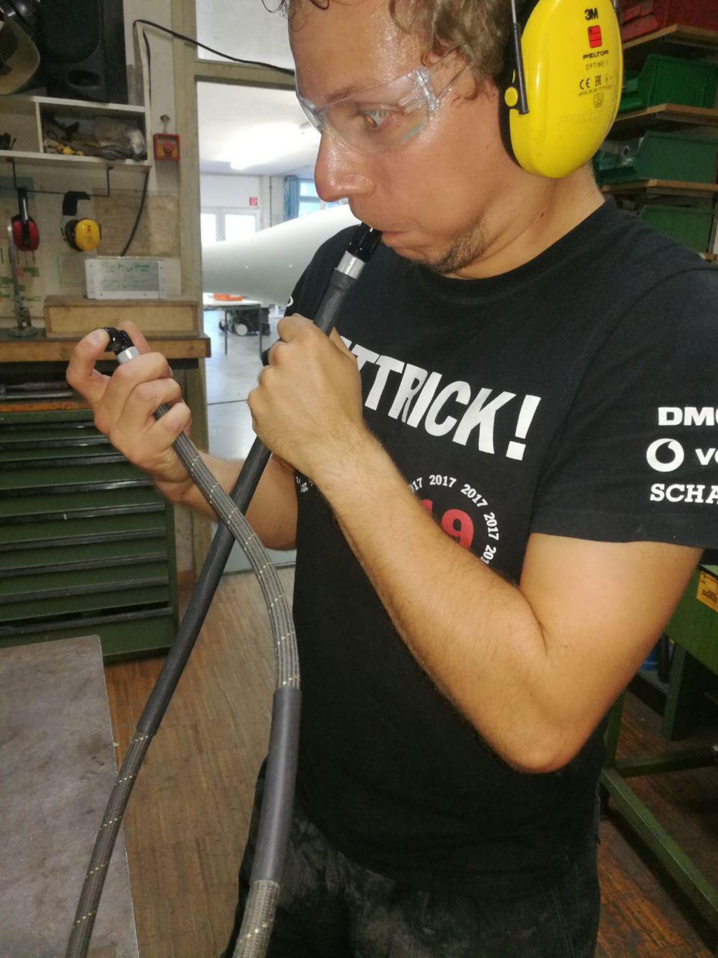
Tight is Right
Since the assembly of the fuel hoses had to wait on other other parts being installed, their installation was somewhat delayed. Therefore, these could be manufactured by hand in the workshop. The possibility to adapt the respective hose directly in the fuselage promises a higher probability of success than ordering one from America with inaccurate measurements with threads and rulers in the fuselage. In addition, fire protection coating or chafers can be positioned directly in the fuselage. Whether the work was carried out properly is shown at the end of the pressure test. Each component was compressed with air and diesel – so far it looks like we got everything sealed correctly!
Everything for ergonomics
Regulation requires a switch with which the fuel supply from the tank to the engine can be cut in the event of a fire. The rotary knob of this engine fuel shut off valve is located in the center console. In order to avoid fumes in the cockpit due to possible leaks in the fuel system, the fuel will not run through the cockpit itself but in the wing box below. The actual valve for switching off the diesel supply is thus located deep down in the wing box. For the coupling of switch and valve there is now a shaft equipped with cardan joints, which were partly self made, to position the switch ergonomically in the center console. Furthermore, for aesthetic reasons, the lever will point in forward flight direction during normal flight.
Holes in the Fuselage
The hoses that have now been assembled can now also be used for final placement of the drain valve and vent. The drain valve is at the lowest point of the system in order to drain unwanted deposits as part of the pre-flight check. In addition, the appropriate venting device has been installed. This not only allows air to flow into the tank when it is gradually being flown empty, but is also the outlet for excess fuel when an over motivated flight student has overfilled the tank.
When drilling holes in the freshly painted fuselage shell, you must of course be very careful.
Cool Kerosene
There are only experimental values available regarding the temperature rise of the fuel due to compression in the engine. In addition, none of the empirical values can be applied to our configuration. Since a large part of the fuel flows back into the tank with common rail diesel injection, it is reasonable to assume that it will gradually heat up further. Ultimately, we decided to interpose a fuel cooler in the reflux. We are currently working on its installation in the engine compartment. The flight test will tell us whether the cooler is sufficiently dimensioned or whether it is perhaps not necessary at all.